Introduction

More than ten years ago now, when I decided to setup a large front projection
Home Theatre style system, I
needed some kind of subwoofer for the surround sound system to make use of all
the THX Laserdiscs I had been
collecting in
Atlanta GA while I was working there with
BT/Concert. I ended up buying a lot of equipment form
Jeffries Hi-Fi
in Eastbourne because that was the nearest place I could get the
Seleco projector that I wanted.
I asked what type of subwoofer they would use for a large system like the one I
was building and they suggested REL
who made quite a range. As I was somewhat dubious about adding any kind of
subwoofer to the system I asked if I could borrow one. After a while they
got me a demo unit from REL which
was a Stentor model
and was the largest they had ever sold at the time. In those days, the Stentor
was a was working there with
BT/Concert. I ended up buying a lot of equipment form
Jeffries Hi-Fi
in Eastbourne because that was the nearest place I could get the
Seleco projector that I wanted.
I asked what type of subwoofer they would use for a large system like the one I
was building and they suggested REL
who made quite a range. As I was somewhat dubious about adding any kind of
subwoofer to the system I asked if I could borrow one. After a while they
got me a demo unit from REL which
was a Stentor model
and was the largest they had ever sold at the time. In those days, the Stentor
was a
 200
watt MOSFET system with a 10 inch Volt down firing driver in a 72 liter bass
reflex enclosure. It looks like the latest version is very similar but 200
watt MOSFET system with a 10 inch Volt down firing driver in a 72 liter bass
reflex enclosure. It looks like the latest version is very similar but now
with a 300 watt amp. I connected the Stentor
into my system that also consisted of my
Velleman K4000 tube
amp and my Quad ESL-63
speakers and started to set it up as REL describe in their
manual.
This consists of the setting of three controls on the amp of the subwoofer.
Two of them control the upper crossover frequency (from 30Hz to 120Hz in 10%
steps), one course adjustment and one fine. The other control is for the
gain. The Stentor
has a line level input that I connected to my Pioneer SP-700D ProLogic
processor full range mono output or if you need to it also has a pair of speaker level
inputs to connect from the power amp output directly if needed. It took
quite some messing around with the controls but after a while I got it so it
sounded quite good although I ended up setting it to now
with a 300 watt amp. I connected the Stentor
into my system that also consisted of my
Velleman K4000 tube
amp and my Quad ESL-63
speakers and started to set it up as REL describe in their
manual.
This consists of the setting of three controls on the amp of the subwoofer.
Two of them control the upper crossover frequency (from 30Hz to 120Hz in 10%
steps), one course adjustment and one fine. The other control is for the
gain. The Stentor
has a line level input that I connected to my Pioneer SP-700D ProLogic
processor full range mono output or if you need to it also has a pair of speaker level
inputs to connect from the power amp output directly if needed. It took
quite some messing around with the controls but after a while I got it so it
sounded quite good although I ended up setting it to the minimum value of 30Hz. Its cool to listen to CD's you've been listening to
for years and suddenly hear deep bass that you never knew existed, so I was
quite pleased with it! It's also worth pointing out that most CD's I
listened to where I expected to hear something different, sounded just the same. Next I the minimum value of 30Hz. Its cool to listen to CD's you've been listening to
for years and suddenly hear deep bass that you never knew existed, so I was
quite pleased with it! It's also worth pointing out that most CD's I
listened to where I expected to hear something different, sounded just the same. Next I cranked up the system and watched the
Peter Gabriel Real World tour concert on
Laserdisc with digital audio. Wow! Holy cow!! It was
fantastic, so I cranked it up some more to see if something would break before
Susan told me it was too loud!
Luckily, Susan likes Peter Gabriel so the
REL was in for a real test of
guts. Well, the thundering dynamics of
Tony Levin's fantastic
collection of bass guitars very shortly proved to be far too much for the
REL, and the
Velleman K4000 tube amp and the
Quad ESL-63 speakers were just blazing past
it! The poor Volt driver was popping all over the place and I was sure it
was going to bust a gut if I were to continue! Sorry
REL Stentor,
audition failed! Having said that, the
REL Stentor
did have a good sound and still receives
good
reviews
(if you believe those),
but to be beaten down by a tube amp and electrostatic speakers is nothing short
of embarrassing for any subwoofer! Even
Susan asked why I was turning it down! Not only that, they go these
days for about $5000 which I consider to be totally ridiculous considering the
performance.
cranked up the system and watched the
Peter Gabriel Real World tour concert on
Laserdisc with digital audio. Wow! Holy cow!! It was
fantastic, so I cranked it up some more to see if something would break before
Susan told me it was too loud!
Luckily, Susan likes Peter Gabriel so the
REL was in for a real test of
guts. Well, the thundering dynamics of
Tony Levin's fantastic
collection of bass guitars very shortly proved to be far too much for the
REL, and the
Velleman K4000 tube amp and the
Quad ESL-63 speakers were just blazing past
it! The poor Volt driver was popping all over the place and I was sure it
was going to bust a gut if I were to continue! Sorry
REL Stentor,
audition failed! Having said that, the
REL Stentor
did have a good sound and still receives
good
reviews
(if you believe those),
but to be beaten down by a tube amp and electrostatic speakers is nothing short
of embarrassing for any subwoofer! Even
Susan asked why I was turning it down! Not only that, they go these
days for about $5000 which I consider to be totally ridiculous considering the
performance.
Reverse Engineering
 Well, seeing as the REL Stentor
was just lying there with it's feet in the air, I decided that some open heart
surgery was in order to see what made it tick before I returned it to the shop! Unfortunately, there were
of course no digital cameras back then, so I'll just have to describe what I
found as best as I can remember. Inside the layout was much as expected.
Class B MOSFET amp built into the back plate with an active low pass filter, a
well built and heavily braced cabinet lined with acoustic absorbing fiber with a
single bass reflex port and the 10 inch Volt driver. As I indicated above,
it looked like the Volt driver was the weakest component although some of the
blame lies with the front end active filter in that it was only a low pass
design and did not provide a band pass so that the subsonic frequencies that
were popping the Volt could have been avoided as there is no loading for the
speaker cone from a bass reflex cabinet at such low frequencies. The bass
on the digital audio sound track of the Laserdisc was so good that you could
actually see the Volt bass driver slowly moving under the pressure of
Tony Levin's thumb
resting on the strings of his bass even when no notes were actually being played
in between the songs! Looking at all the guts of the
REL laying there it struck me
that it wouldn't be hard to build a much bigger and better system myself for a
fraction of the cost! MOSFET's, operational amps, bass guitar speakers &
wood are not that expensive to buy! Of course, replicating the high
quality wood finish of the cabinet would be hard, but I was more interested in
the quality of the sound than the appearance. With that in mind, I set about
investigating the main mysterious component of the system: The adjustable active
low pass filter which
REL proudly refer to as ABC
(Adjustable Bass Control) as this did not appear to be an item I could buy
off-the-shelf. Well, seeing as the REL Stentor
was just lying there with it's feet in the air, I decided that some open heart
surgery was in order to see what made it tick before I returned it to the shop! Unfortunately, there were
of course no digital cameras back then, so I'll just have to describe what I
found as best as I can remember. Inside the layout was much as expected.
Class B MOSFET amp built into the back plate with an active low pass filter, a
well built and heavily braced cabinet lined with acoustic absorbing fiber with a
single bass reflex port and the 10 inch Volt driver. As I indicated above,
it looked like the Volt driver was the weakest component although some of the
blame lies with the front end active filter in that it was only a low pass
design and did not provide a band pass so that the subsonic frequencies that
were popping the Volt could have been avoided as there is no loading for the
speaker cone from a bass reflex cabinet at such low frequencies. The bass
on the digital audio sound track of the Laserdisc was so good that you could
actually see the Volt bass driver slowly moving under the pressure of
Tony Levin's thumb
resting on the strings of his bass even when no notes were actually being played
in between the songs! Looking at all the guts of the
REL laying there it struck me
that it wouldn't be hard to build a much bigger and better system myself for a
fraction of the cost! MOSFET's, operational amps, bass guitar speakers &
wood are not that expensive to buy! Of course, replicating the high
quality wood finish of the cabinet would be hard, but I was more interested in
the quality of the sound than the appearance. With that in mind, I set about
investigating the main mysterious component of the system: The adjustable active
low pass filter which
REL proudly refer to as ABC
(Adjustable Bass Control) as this did not appear to be an item I could buy
off-the-shelf.
The REL ABC filter
Component by component investigation showed that the
REL ABC filter consisted simply
of three DC coupled operational amplifier stages each using one half of a
TL072 operational amplifier
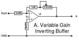
device. I have drawn a simplified diagram of each stage that excludes the
power. The first stage was a variable gain inverting buffer. The
100K potentiometer shown is the level control knob.
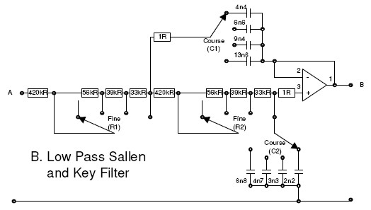
The next stage was a unity gain low pass second order Sallen and Key filter.
The four position course frequency adjuster was a dual gang rotary switch that
simultaneously changed the values of C1 & C2 in the filter always keeping C1
double the value of C2. The four position fine frequency adjuster was a
dual gang rotary switch that simultaneously changed the values of R1 and R2
always keeping R1 equal to R2. When C1 = 2*C2 and R1= R2, it gives the
filter a Butterworth frequency response. The mathematics that describe the
filter are shown
here.
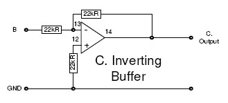
The third and final stage was a unity gain inverting buffer which in
combination with the previous stages caused the output to have the same phase as
the input and gave a suitable output impedance to match with the input of the
power amp.
| Course |
Fine |
Frequency Hz |
| 1 |
1 |
30 |
| 1 |
2 |
33 |
| 1 |
3 |
36 |
| 1 |
4 |
39 |
| 2 |
1 |
43 |
| 2 |
2 |
47 |
| 2 |
3 |
52 |
| 2 |
4 |
57 |
| 3 |
1 |
62 |
| 3 |
2 |
67 |
| 3 |
3 |
73 |
| 3 |
4 |
80 |
| 4 |
1 |
90 |
| 4 |
2 |
100 |
| 4 |
3 |
110 |
| 4 |
4 |
120 |
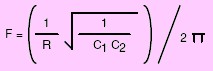
REL provide
this table
as a guide to the crossover frequencies applied by the various switch settings
and these are inline with the formula shown. This formula only works when
R1 = R2 and C1 = 2 X C2. Since it was professors R.P. Sallen and E.L. Key that first described
the Sallen & Key low-pass filter in 1955, and it's implementation in operational
amplifier based active filters designs is openly described in the datasheets of
the companies who produce such devices, there is clearly nothing special or
anything proprietary to
REL in this design and as
TL072's
are just 26 cents a piece, the whole filter can be made for pocket change!
Hmm.., now I'm really on
REL's case about the ratio of
cost to performance with the Stentor!
Also, as you might imagine, changing the settings on those rotary switches while
the amp is on causes a frightening pop from the poor Volt speaker! So you
need to power it down each time before changing the setting which can make the
whole process somewhat tedious.
Do It Yourself Bass!
Now knowing all about the active filter part, I just had to design my own
board, find a suitable
driver, an amplifier and a cabinet design so that I could build my own super
version of the basic REL Stentor. That was all as easy as just
picking up the
Maplin catalog!
Maplin carry an enormous
range of components and equipment and I still order things from them now even
though I am in the U.S.A. and this is a description of the system I built.
The Driver
   I turned to the speaker section and looked for the biggest most powerful
bass driver that
Maplin had to offer!
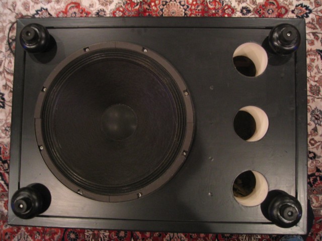
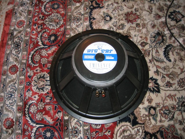
It turned out to be a 400 watt 18 inch Big Cat bass guitar speaker made by
Eminence in the U.S.A. It looks like they don't make the same unit anymore
but it is a big heavy cast frame speaker with an enormous magnet and a four inch
voice coil that is vented through the back of the magnet! The current
Sigma Pro 18 looks most like it although that one is 650 watts. It
looks totally awesome from either side. The tiny 10 inch Volt driver from
the REL Stentor
looked like a little toy by comparison! The
Thiele & Small parameters indicated the the speaker had a resonant frequency
of 33.5Hz and this was the only parameter I looked at and I just designed the
cabinet to have the same resonant frequency. At the time, it cost 129.99
British pounds (about $195). I turned to the speaker section and looked for the biggest most powerful
bass driver that
Maplin had to offer!
It turned out to be a 400 watt 18 inch Big Cat bass guitar speaker made by
Eminence in the U.S.A. It looks like they don't make the same unit anymore
but it is a big heavy cast frame speaker with an enormous magnet and a four inch
voice coil that is vented through the back of the magnet! The current
Sigma Pro 18 looks most like it although that one is 650 watts. It
looks totally awesome from either side. The tiny 10 inch Volt driver from
the REL Stentor
looked like a little toy by comparison! The
Thiele & Small parameters indicated the the speaker had a resonant frequency
of 33.5Hz and this was the only parameter I looked at and I just designed the
cabinet to have the same resonant frequency. At the time, it cost 129.99
British pounds (about $195).
The Amplifier
 For
the amplifier, I decided to buy a
K4010 Velleman kit so that I could build the amp and filter electronics all
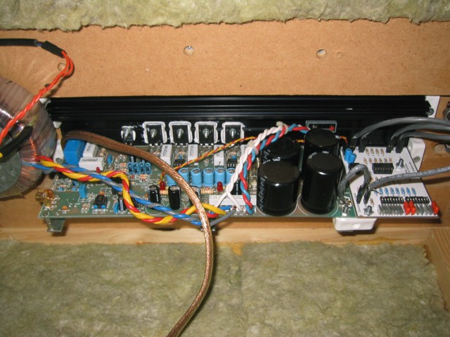
together. The
K4010 is a powerful 300 watt MOSFET amplifier with a large toriodal core
transformer and a pair of 10,000 uF capacitors in the power supply. There
is also space to For
the amplifier, I decided to buy a
K4010 Velleman kit so that I could build the amp and filter electronics all
together. The
K4010 is a powerful 300 watt MOSFET amplifier with a large toriodal core
transformer and a pair of 10,000 uF capacitors in the power supply. There
is also space to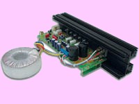 add an additional pair of 10,000uF capacitors to make a total of 40,000uF for
the one mono channel. That's a lot! Take a look into your main power
amp and see what you have for each channel! This means that the output impedance of the
amplifier is reduced even further which will increase the damping factor.
Even without the extra capacitors, the damping factor of the amp is over 600!!
The damping factor of an amplifier is one of the main parameters that effect the
quality of bass sometimes referred to as tightness of bass. The base is
tighter (less floppy and fumbled sounding) literally because the amplifier is
able to move the large motor of the speaker more exactly (especially when it
comes to reversing
add an additional pair of 10,000uF capacitors to make a total of 40,000uF for
the one mono channel. That's a lot! Take a look into your main power
amp and see what you have for each channel! This means that the output impedance of the
amplifier is reduced even further which will increase the damping factor.
Even without the extra capacitors, the damping factor of the amp is over 600!!
The damping factor of an amplifier is one of the main parameters that effect the
quality of bass sometimes referred to as tightness of bass. The base is
tighter (less floppy and fumbled sounding) literally because the amplifier is
able to move the large motor of the speaker more exactly (especially when it
comes to reversing
 he direction of movement) because the voltage output by
the MOSTET output stage is mostly dropped across the impedance of the speakers
voice coil of 8 ohms, rather that burnt in the internal resistance of the
amplifier. So an amplifier with a damping factor of 600 at 8 ohms has an
output impedance of 8/600 = 13.3 milliohms! Compare that to a high end
power amp like the Technics SE-A5 that has
a damping factor of 140 and you can see how well suited this amp is for a
subwoofer application. The single board of the amp is directly mounted to
the large heat sink and this layout is well suited to allow the back of the heat
sink to stick through a slot in the back of the subwoofer cabinet. Also
the
K4010 Velleman design uses
TL072
operational amplifiers on its front end and so has a high quality -18 volt & +18
volt supply line for them. As these are the same devices that will be used
to make the active filter, this will make it easy to power the filter from
the main amp board. Not only that, but there is some space for a small
extra board to be mounted onto the heat sink along side the main amp board, so
this will be a perfect location to mount the active filter. The
K4010 is in fact half of a
K4020
without the case so the construction is the same as shown in the
K4020 manual. At the time, it cost 134.99 British pounds (about $202). he direction of movement) because the voltage output by
the MOSTET output stage is mostly dropped across the impedance of the speakers
voice coil of 8 ohms, rather that burnt in the internal resistance of the
amplifier. So an amplifier with a damping factor of 600 at 8 ohms has an
output impedance of 8/600 = 13.3 milliohms! Compare that to a high end
power amp like the Technics SE-A5 that has
a damping factor of 140 and you can see how well suited this amp is for a
subwoofer application. The single board of the amp is directly mounted to
the large heat sink and this layout is well suited to allow the back of the heat
sink to stick through a slot in the back of the subwoofer cabinet. Also
the
K4010 Velleman design uses
TL072
operational amplifiers on its front end and so has a high quality -18 volt & +18
volt supply line for them. As these are the same devices that will be used
to make the active filter, this will make it easy to power the filter from
the main amp board. Not only that, but there is some space for a small
extra board to be mounted onto the heat sink along side the main amp board, so
this will be a perfect location to mount the active filter. The
K4010 is in fact half of a
K4020
without the case so the construction is the same as shown in the
K4020 manual. At the time, it cost 134.99 British pounds (about $202).
The Active Low Pass Filter (Rev A)
| Course |
Fine |
Frequency Hz |
| 1 |
1 |
17 |
| 1 |
2 |
19 |
| 1 |
3 |
20 |
| 1 |
4 |
22 |
| 2 |
1 |
30 |
| 2 |
2 |
34 |
| 2 |
3 |
37 |
| 2 |
4 |
39 |
| 3 |
1 |
44 |
| 3 |
2 |
49 |
| 3 |
3 |
53 |
| 3 |
4 |
57 |
| 4 |
1 |
62 |
| 4 |
2 |
69 |
| 4 |
3 |
75 |
| 4 |
4 |
81 |
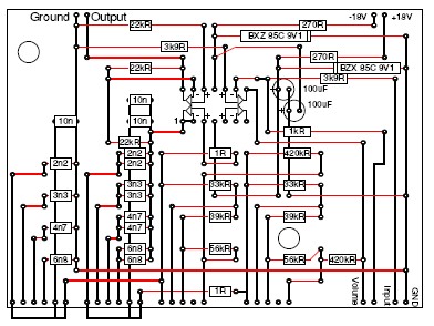
As you might
expect if you have read this far, the active filter I built was based on the
REL Stentor
design. Originally in 1994, the version that I built was pretty much an
exact copy of the REL but made on a piece of
grid style copper clad breadboard that was cut to be
3.9 X 2.8 inches,
which fitted into the available space on the
K4010 Velleman amp. The lines shown in black were the connected solder
pads on the back of the board and the red lines are where the wire straps that were on
the front. Rather than using a pair of
TL072
op amps, I used a single TL074
that had four matched devices in a single chip and left one of them unused. I connected up two
rotary two pole switches like the REL and connected them to the board with
screened multicore cable. Once the system was working, by trial and error
I found that I needed a crossover frequency of just 17Hz where R1 = R2 = 548K
and C1 = 24n4 and C2 = 12n2. Of course, the
REL Stentor
version
 did not support such a low crossover frequency, and so I had to add
an extra 10n and 20n capacitor (two 10n in parallel) afterwards.
To make the lowest position on the switch make C1 = 24n2 and C2 = 12n2, I setup
the connections to the switch so that the necessary capacitors (2n2 & 4n4) were
connected in parallel with the 10n and 20n capacitor. This now makes the did not support such a low crossover frequency, and so I had to add
an extra 10n and 20n capacitor (two 10n in parallel) afterwards.
To make the lowest position on the switch make C1 = 24n2 and C2 = 12n2, I setup
the connections to the switch so that the necessary capacitors (2n2 & 4n4) were
connected in parallel with the 10n and 20n capacitor. This now makes the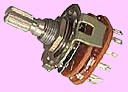 whole chart look like the one shown and causes a bit of a gap in between
22Hz and 30Hz which makes no difference in my case, but these issues are
resolved in my more recent Rev B version.
You could easily arrange the capacitor values to give any size steps you may
need. I also added a couple of
9.1
volt zener diodes (shown as BZX 95C 9V1 above) and 270 ohm resistors to
form a simple regulator for the
TL072
power supply at 9.1 volts. In fact I have since found that these are not
necessary and the
TL072
can be connected directly to the +18 & -18 volt lines on the
K4010 Velleman. So just put a wire strap in that place and omit the
270 ohm resistors. The diagram here should be sufficient for you to build
your own version if you wish. Let me
know if you have any questions! At the time, this board cost almost
nothing to make!
whole chart look like the one shown and causes a bit of a gap in between
22Hz and 30Hz which makes no difference in my case, but these issues are
resolved in my more recent Rev B version.
You could easily arrange the capacitor values to give any size steps you may
need. I also added a couple of
9.1
volt zener diodes (shown as BZX 95C 9V1 above) and 270 ohm resistors to
form a simple regulator for the
TL072
power supply at 9.1 volts. In fact I have since found that these are not
necessary and the
TL072
can be connected directly to the +18 & -18 volt lines on the
K4010 Velleman. So just put a wire strap in that place and omit the
270 ohm resistors. The diagram here should be sufficient for you to build
your own version if you wish. Let me
know if you have any questions! At the time, this board cost almost
nothing to make!
The Cabinet
| Internal Height |
16 Inches |
| Internal Width |
37 Inches |
| Internal Depth |
26 Inches |
| Wall Thickness |
1 1/2 & 3/4 Inch |
| Internal Volume |
8.9 Cubic Feet |
| Resonant Frequency |
32 |
| Number of Ports |
3 |
| Port Diameter |
4 Inches |
| Port Length |
6 Inches |
| Weight |
Very Very Heavy!! |
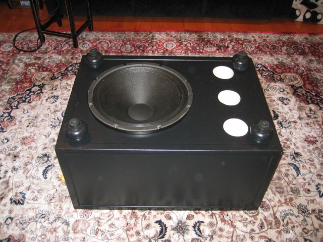
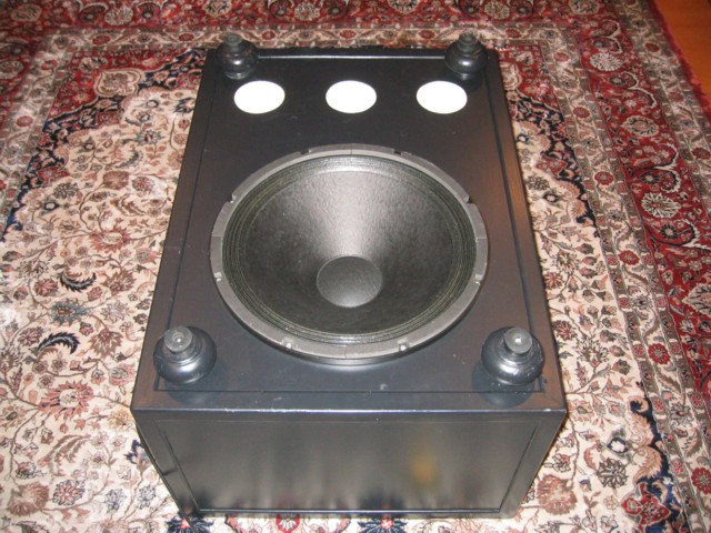
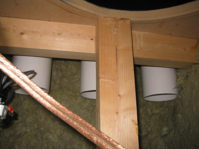
For the cabinet I followed the same general layout as the REL, that is a
down firing woofer with the bass reflex port in the baffle with the driver and
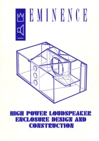
the amplifier mounted through the rear of the cabinet. As I needed some
information about how to work out the porting, I purchased a book called
"Eminence High Power Loudspeaker Enclosure Design and Construction" (ISBN 0
9518252 1 6). This contained all I needed to know and only cost 9.95
British pounds from
Maplin. This book may
or may not be in print any longer, but as you can see from the cover, it has
some interesting designs. It has various mathematical information and
graphs and charts that enable you to work out the diameter, length and number of
bass reflex ports needed in the cabinet for a given box volume and a required
resonant frequency. There are also various alignment charts for SBB4, QB3
and C4 alignments that enable you to work out what frequency to tune the cabinet
to based on the drivers
Thiele & Small parameters. This is all done with rulers and
pencils in an old fashion slide rule style! In the end, I just decided to
tune the cabinet to 33.5Hz to match the resonant frequency of the driver and
this resulted in a box as shown in the table. These days there is various
software that can work all this out for you very accurately like
Eminence Designer. In fact I now know from using
Eminence Designer that my box is actually tuned to 32Hz, rather than 33.5Hz,
but the charts in the book were pretty close! I built the cabinet from
heavy & dense 3/4 inch MDF. As far as I can see, the kind of MDF
 you
get from Lowes or Home Depot in the U.S.A. is nothing as dense at the stuff you
can get in England, which is more like HDF and is much heavier. All of the
sides except the baffle were double layered making the sides 1 1/2 inches thick
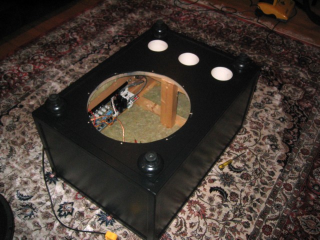
and the whole thing weighs a ton! I also put a 4x2 brace across the baffle
in between the speaker and the ports and another under the top of the cabinet in
the same location. Then in between those two braces I added another 4x2 to
make an H shaped brace. In other words, it's built like a "Brick
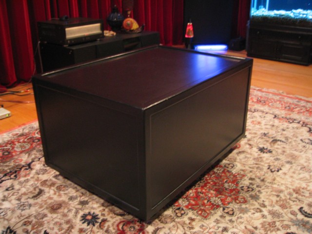
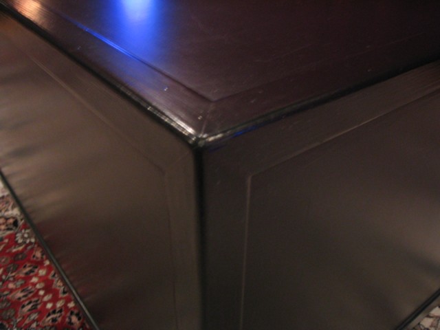
Shit House" as they say in England! Then I covered all the outside edges with an L style cross section molding mitered at each corner.
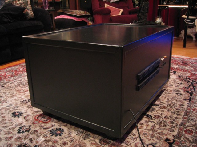
Then I fitted four big heavy feet that I got from an old dresser. Next the
whole thing was painted with a furniture grade black satin Teflon paint and I
must say, it looks great! Where the molding goes around the top, I put an
extra strip of flat molding under the corner molding so it is raised more so
that there is sufficient depth for the glass top to sit, although now ten years
later, I still haven't got around to getting that glass top cut! Where the
amplifier heat sink fits through a slot I cut in the back, It is secured with
small plastic cube blocks intended for fitting shelves and then the small gap
around the heat sink is sealed with black silicone sealer to prevent any leaks.
In fact I did test the subwoofer before sealing that gap and you wouldn't
believe the howling sound that air makes as it goes in and out of the slot!
This shows that there is good reason why the reflex ports must be of a certain
minimum diameter to maintain port air velocity at a sub sonic level! All
of the wood, moldings and paint came to just under 100 British pounds (about
$150). you
get from Lowes or Home Depot in the U.S.A. is nothing as dense at the stuff you
can get in England, which is more like HDF and is much heavier. All of the
sides except the baffle were double layered making the sides 1 1/2 inches thick
and the whole thing weighs a ton! I also put a 4x2 brace across the baffle
in between the speaker and the ports and another under the top of the cabinet in
the same location. Then in between those two braces I added another 4x2 to
make an H shaped brace. In other words, it's built like a "Brick
Shit House" as they say in England! Then I covered all the outside edges with an L style cross section molding mitered at each corner.
Then I fitted four big heavy feet that I got from an old dresser. Next the
whole thing was painted with a furniture grade black satin Teflon paint and I
must say, it looks great! Where the molding goes around the top, I put an
extra strip of flat molding under the corner molding so it is raised more so
that there is sufficient depth for the glass top to sit, although now ten years
later, I still haven't got around to getting that glass top cut! Where the
amplifier heat sink fits through a slot I cut in the back, It is secured with
small plastic cube blocks intended for fitting shelves and then the small gap
around the heat sink is sealed with black silicone sealer to prevent any leaks.
In fact I did test the subwoofer before sealing that gap and you wouldn't
believe the howling sound that air makes as it goes in and out of the slot!
This shows that there is good reason why the reflex ports must be of a certain
minimum diameter to maintain port air velocity at a sub sonic level! All
of the wood, moldings and paint came to just under 100 British pounds (about
$150).
Response Analysis
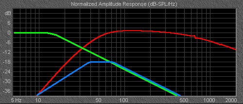
Now let's have a look at the overall response of the system. The graph
shown in red here is produced by
Eminence Designer from the
Thiele & Small parameters of the original Big Cat driver that I got from
the 1994
Maplin catalogue, and is
zoomed in on the region from 5Hz to 2000Kz as we are not interested in anything
beyond that for a subwoofer. This response curve is based on a
mathematical calculation of the driver parameters combined with the actual box
and port design. As you can see, the design gives a soothe Butterworth
curve with a corner frequency of about 55Hz and then drops smoothly down to
10Hz, so this is the response you could expect if you just connected the speaker
to an amplifier without a filter. Next, I plotted the green line that
shows the response curve of the Active Filter which as I said above, I ended up
setting to 17Hz. So as you would expect, the corner frequency is 17Hz
where the level is -3dB and after that the level decreases a further -6dB
(second-order) for every octave being -39dB at 400Hz at the limit of this graph.
Next, I plotted the blue line that shows the aggregate effect of the other two
lines which is what we will get when the active filter and the speaker are in
series. As you can see, what you get is in fact a band pass effect with a
Butterworth response at each end and corner frequencies of about 35Hz and 80Hz
with the pass band being flat at -18dB. This is quite a surprise to people
who think they have their subwoofer set to a very low crossover frequency and
that that frequency alone dictates the response of the entire system!
Clearly this is not so. By adjusting the volume control to give the gain
stage of the filter something approaching 18dB of gain brings the flat pass band
pass portion up to the level of the other speakers in the system and this is
close to the optimum setting although the bass amp in the subwoofer will be
working much harder that the amps in the rest of the system. So what kind
of
 passive
crossover has a gain of 18dB? None of course! And this is why active
subwoofer systems can take bass where there has never been any before. It
makes no difference how big and powerful your main speakers are, it just isn't
possible to compete with an active subwoofer! So overall, what we have
here is a subwoofer system that has an upper corner frequency of 80Hz with a
second order Butterworth response falling off at 6dB per octave. It would
be possible to increase the maximum music power handling of the system by employing a high
pass shelf filter in the region below 8Hz or so and this is definitely what the REL Stentor
could do with. However in the case of my design, the speaker is so big and
powerful compared with everything else, that I have never noted any issues with
the speaker cone popping although this is clearly a possibility if the system
was to be used in a large venue, but for domestic use, it's fine as it is.
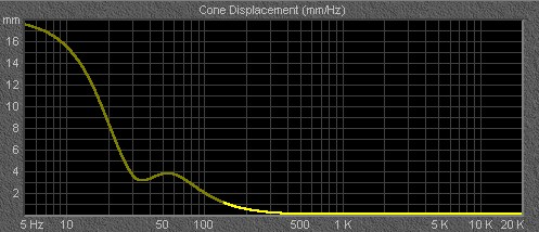
The Cone Displacement graph above shows the actual amount of cone movement, and
as you can see, this rises sharply at frequencies below the resonant frequency
of the driver. Another point is that the existing design is also capable
of reproducing deep subsonic pressure waves especially when standing in a room
with wooden floors. This is the sound that you "feel" when you see those
big explosions on THX films or
listen to music like R Kelly
and this ability would be reduced by employing a high pass shelf filter. passive
crossover has a gain of 18dB? None of course! And this is why active
subwoofer systems can take bass where there has never been any before. It
makes no difference how big and powerful your main speakers are, it just isn't
possible to compete with an active subwoofer! So overall, what we have
here is a subwoofer system that has an upper corner frequency of 80Hz with a
second order Butterworth response falling off at 6dB per octave. It would
be possible to increase the maximum music power handling of the system by employing a high
pass shelf filter in the region below 8Hz or so and this is definitely what the REL Stentor
could do with. However in the case of my design, the speaker is so big and
powerful compared with everything else, that I have never noted any issues with
the speaker cone popping although this is clearly a possibility if the system
was to be used in a large venue, but for domestic use, it's fine as it is.
The Cone Displacement graph above shows the actual amount of cone movement, and
as you can see, this rises sharply at frequencies below the resonant frequency
of the driver. Another point is that the existing design is also capable
of reproducing deep subsonic pressure waves especially when standing in a room
with wooden floors. This is the sound that you "feel" when you see those
big explosions on THX films or
listen to music like R Kelly
and this ability would be reduced by employing a high pass shelf filter.
The Sound and Current Usage
 No words can describe how blown away I was when I first powered up my new
homemade subwoofer! Although it took a couple of days of messing around
with the filter settings, once it was set, it sounded simply fantastic!
The bass was smooth and tight like nothing I had ever heard and it went way down
to the center of the Earth! At the same time, music that did not have much
or any deep base was totally unaffected by the subwoofers presence and there
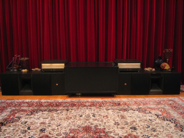
were no negative coloration effects at all that I could note! It blended
perfectly with the Velleman K4000 &
Quad ESL-63 speakers that I use as my main
front stereo system. I quickly
decided to test it with the
Peter Gabriel Real World tour concert
and found that at last I had a system that could reproduce the proper sound of
the concert without blowing up!!
THX movies where of course great
fun with bundles of deep base that were previously unnoticed. An interesting point to note is that the
Quad ESL-63 speakers are not exactly noted
for their bass, yet I had to have the crossover frequency of the active filter
on the subwoofer set to a very low 17Hz to balance the system, and I found
myself setting the REL Stentor
in the same general way. This indicates to me that other people are either
using very small front speakers or have their subwoofers set at too high a
frequency and are overlapping a lot with their main system. I never ever imagined that
the sound could be so good and
that I would be so pleased with it as I only intended for it to be an experimental
prototype. I thought that I would be driven to continue experimenting and
messing about with
it and that it would take at least months if not years to get it right!
Apparently not, and the same design with the original paint (and still no glass
top) is still working in my current system
at Chester River today!
This is probably due in part to using absolute top quality components and paying
particular attention to design details and build quality and I had great fun
doing it! Still most people who don't know how speakers really work (and
even those that do!) are intrigued about how good it is and find it difficult to
grasp that I actually did design and build this thing myself! Seeing as it
all cost little more than 400 British pounds in 1994 (about $600) including the
electronics, speaker, wood and everything and the REL Stentor
cost 1595 (about $2392), it just goes to show how much meat you actually get in a commercial
product with my version costing only 1/4 the amount and being infinitely better!
Over the years there have been many times the subwoofer has accidentally been
left switched on for days at a time and it has been subjected to some extreme
temperatures while in storage on some occasions. Even so, it has never
ever failed to operate perfectly and I'm sure it will run long and loud for many
years to come! More recently while setting up what I intended to be a
THX system at Chester River,
I discovered what I consider to be a fundamental flaw in the
THX specification (at lease for
stereo music use), and due to
this I had to build a new active filter in order to properly integrate the
subwoofer with my new Marantz AV-9000 preamp and this is described here. No words can describe how blown away I was when I first powered up my new
homemade subwoofer! Although it took a couple of days of messing around
with the filter settings, once it was set, it sounded simply fantastic!
The bass was smooth and tight like nothing I had ever heard and it went way down
to the center of the Earth! At the same time, music that did not have much
or any deep base was totally unaffected by the subwoofers presence and there
were no negative coloration effects at all that I could note! It blended
perfectly with the Velleman K4000 &
Quad ESL-63 speakers that I use as my main
front stereo system. I quickly
decided to test it with the
Peter Gabriel Real World tour concert
and found that at last I had a system that could reproduce the proper sound of
the concert without blowing up!!
THX movies where of course great
fun with bundles of deep base that were previously unnoticed. An interesting point to note is that the
Quad ESL-63 speakers are not exactly noted
for their bass, yet I had to have the crossover frequency of the active filter
on the subwoofer set to a very low 17Hz to balance the system, and I found
myself setting the REL Stentor
in the same general way. This indicates to me that other people are either
using very small front speakers or have their subwoofers set at too high a
frequency and are overlapping a lot with their main system. I never ever imagined that
the sound could be so good and
that I would be so pleased with it as I only intended for it to be an experimental
prototype. I thought that I would be driven to continue experimenting and
messing about with
it and that it would take at least months if not years to get it right!
Apparently not, and the same design with the original paint (and still no glass
top) is still working in my current system
at Chester River today!
This is probably due in part to using absolute top quality components and paying
particular attention to design details and build quality and I had great fun
doing it! Still most people who don't know how speakers really work (and
even those that do!) are intrigued about how good it is and find it difficult to
grasp that I actually did design and build this thing myself! Seeing as it
all cost little more than 400 British pounds in 1994 (about $600) including the
electronics, speaker, wood and everything and the REL Stentor
cost 1595 (about $2392), it just goes to show how much meat you actually get in a commercial
product with my version costing only 1/4 the amount and being infinitely better!
Over the years there have been many times the subwoofer has accidentally been
left switched on for days at a time and it has been subjected to some extreme
temperatures while in storage on some occasions. Even so, it has never
ever failed to operate perfectly and I'm sure it will run long and loud for many
years to come! More recently while setting up what I intended to be a
THX system at Chester River,
I discovered what I consider to be a fundamental flaw in the
THX specification (at lease for
stereo music use), and due to
this I had to build a new active filter in order to properly integrate the
subwoofer with my new Marantz AV-9000 preamp and this is described here.
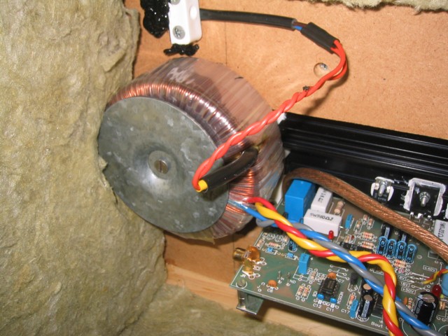
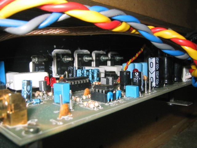
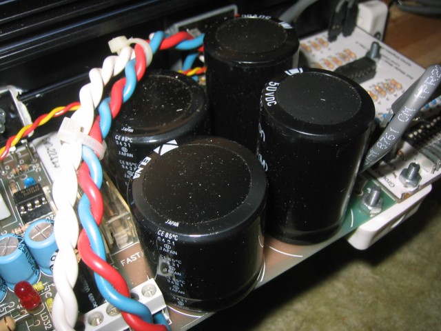
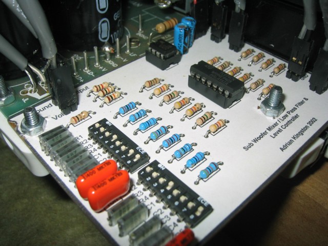
Pictures
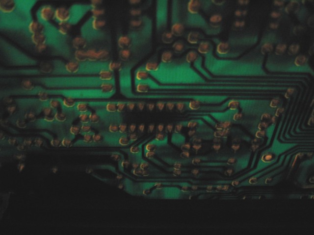
The internal pictures show the newer Rev B version of my active low pass filter
& mixer that is described here.
|