Introduction
 This
page describes the inner workings of the NEC Infrared remote control
transmission format as implemented by Pioneer that is used to communicate
button presses from Pioneer remote control handsets to Pioneer and Pioneer
Elite Audio and
Video equipment. Variants of the same protocol are used by several
Japanese Audio Video manufactures, the most notable variation being the
carrier frequency used, although changing the carrier by changing the
frequency of the crystal in the handset also changes the time base of the
whole frame size. This information could be used to emulate a lost
handset with a computer or a smartphone, This
page describes the inner workings of the NEC Infrared remote control
transmission format as implemented by Pioneer that is used to communicate
button presses from Pioneer remote control handsets to Pioneer and Pioneer
Elite Audio and
Video equipment. Variants of the same protocol are used by several
Japanese Audio Video manufactures, the most notable variation being the
carrier frequency used, although changing the carrier by changing the
frequency of the crystal in the handset also changes the time base of the
whole frame size. This information could be used to emulate a lost
handset with a computer or a smartphone, or if you're just looking to
replace a lost handset, you can
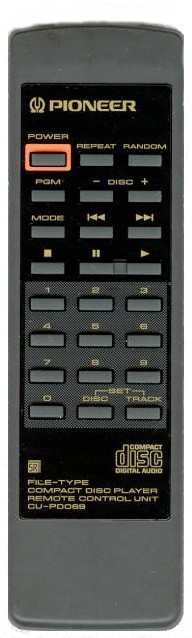
buy a Pioneer remote here at RemoteControlsCenter.com. For the purposes of this description, we'll focus
on the Pioneer CU-P0069, a small and simple remote used with the now old
Pioneer PD-F100 and PD-F904 100
disc CD Changers from 1994. This is of course the reason I had to work all this
out in the first place so that I could emulate the handset with
PCRemote to control the CD
changers from Windows 95 in 1995! The oscilloscope I am using here
to
show the traces is an old
Protek Scope Card 220 running in an ISA slot of my original Windows 95 PC
from 1995, the Acer 2347, a Pentium 133 with 16 Megs of RAM and a 1.6 Gig
hard disk! It still runs today with all of the original hardware and
software! You can see the classic green Acer colors still setup!
While old and slow by today's standards, it boots in a flash and still makes a great digital
storage scope!
or if you're just looking to
replace a lost handset, you can
buy a Pioneer remote here at RemoteControlsCenter.com. For the purposes of this description, we'll focus
on the Pioneer CU-P0069, a small and simple remote used with the now old
Pioneer PD-F100 and PD-F904 100
disc CD Changers from 1994. This is of course the reason I had to work all this
out in the first place so that I could emulate the handset with
PCRemote to control the CD
changers from Windows 95 in 1995! The oscilloscope I am using here
to
show the traces is an old
Protek Scope Card 220 running in an ISA slot of my original Windows 95 PC
from 1995, the Acer 2347, a Pentium 133 with 16 Megs of RAM and a 1.6 Gig
hard disk! It still runs today with all of the original hardware and
software! You can see the classic green Acer colors still setup!
While old and slow by today's standards, it boots in a flash and still makes a great digital
storage scope!
Carrier Frequency
 Like
most (but not all) remote control infrared transmissions, the solid blocks
of time where the light or pulse exists is represented by a flashing LED
rather than a full on LED where the frequency of the flashing is usually
in the range of 30kHz to 50kHz, so that's 30 to 50 thousand flashes a
second. This is done to save power at the transmitter and to make
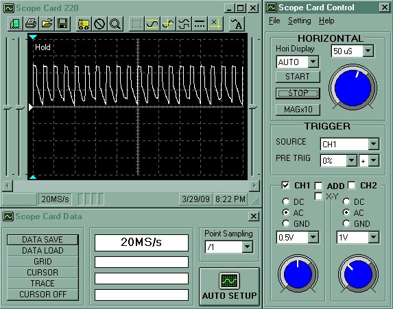
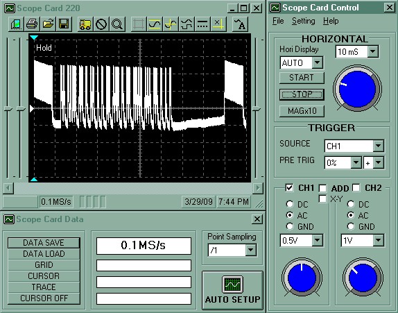
the receiver more effective by blocking out other frequencies. Now let's
see what the CU-P0069 does. All the following traces are produced
just by connecting the oscilloscope probe to the output LED of the
handset. To the left, the scope is zoomed in on the carrier pulses
that are inside a single block of the transmission and as you can see,
there are exactly two pulses for each division on the grid and those
divisions represent 50uS each. So that means that each pulse is 25uS
in length which is 0.000025 of a second. 1 second divided by
0.000025 gives 40,000 pulses for 1 second so the carrier frequency is
40kHz. Like
most (but not all) remote control infrared transmissions, the solid blocks
of time where the light or pulse exists is represented by a flashing LED
rather than a full on LED where the frequency of the flashing is usually
in the range of 30kHz to 50kHz, so that's 30 to 50 thousand flashes a
second. This is done to save power at the transmitter and to make
the receiver more effective by blocking out other frequencies. Now let's
see what the CU-P0069 does. All the following traces are produced
just by connecting the oscilloscope probe to the output LED of the
handset. To the left, the scope is zoomed in on the carrier pulses
that are inside a single block of the transmission and as you can see,
there are exactly two pulses for each division on the grid and those
divisions represent 50uS each. So that means that each pulse is 25uS
in length which is 0.000025 of a second. 1 second divided by
0.000025 gives 40,000 pulses for 1 second so the carrier frequency is
40kHz.
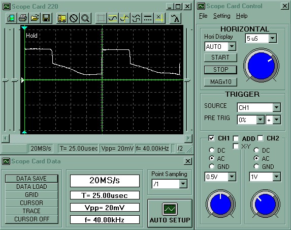 Now
if we zoom in even more on a couple of the pulses we can see that the
pulse fills about 2/5 of the time of the entire cycle so this means that
the duty cycle is about 40%. Also as you can see, the falling edge
of the pulse drops sharply to start with and then falls more slowly.
This is due to the conductive characteristic of the LED and other parts of
the circuit where as the voltage drops, conduction falls off after the
voltage has dropped by about half. A 50% duty cycle gives the best
efficiency and the Pioneer receivers will work with almost any duty cycle
from 30 to 70%. Also in the scope trace to the left, you can see
that I have marked the beginning of the two consecutive pulses with the
green curser line and the scope confirms that f= 40.00kHz by marking the
beginning of each pulse. Now
if we zoom in even more on a couple of the pulses we can see that the
pulse fills about 2/5 of the time of the entire cycle so this means that
the duty cycle is about 40%. Also as you can see, the falling edge
of the pulse drops sharply to start with and then falls more slowly.
This is due to the conductive characteristic of the LED and other parts of
the circuit where as the voltage drops, conduction falls off after the
voltage has dropped by about half. A 50% duty cycle gives the best
efficiency and the Pioneer receivers will work with almost any duty cycle
from 30 to 70%. Also in the scope trace to the left, you can see
that I have marked the beginning of the two consecutive pulses with the
green curser line and the scope confirms that f= 40.00kHz by marking the
beginning of each pulse.
Protocol Frame Pattern
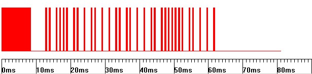
 Now
lets zoom out and look at a complete frame of the protocol pattern.
At this zoom level (10mS per division on the grid) the 40kHz carrier looks
like a solid block of white as the 40kHz pulses are so close together.
You can see that there are three main sections to the complete frame.
1. At the start there is a big block followed by a gap. This section
is called the leader. Now
lets zoom out and look at a complete frame of the protocol pattern.
At this zoom level (10mS per division on the grid) the 40kHz carrier looks
like a solid block of white as the 40kHz pulses are so close together.
You can see that there are three main sections to the complete frame.
1. At the start there is a big block followed by a gap. This section
is called the leader.
2. Then a load of pulses in the middle.
This is the data section 3. Next a long gap. This section is
called the trailer. Then you can see the starting big block of the
next frames leader. Holding the button down repeats the same frame
sequence over and over. This is called Continuous Command
Transmission Mode. The NEC protocol also supports a One-Shot mode
where holding the button down only continues to send the leader, one stop
bit and the trailer, but it appears that Pioneer do not use this.
While it can save battery power in the handset, it means that the receiver
must receive a clear transmission from the very beginning of the button
press.
Leader and Trailer Section

Zooming in to look at the leader shows that it is a solid block lasting
8.45 mS (338 cycles of 40kHz) followed by a gap of 4.225 mS (169 cycles of
40kHz). This is probably intended to be 8mS (320 cycles of 40kHz)
and 4mS (160 cycles of 40kHz) respectively.
To save space on the page here I'll just tell you that the
trailer is just a single stop pulse of 0.5mS (20 cycles of 40kHz) and a gap of 25mS (1000 cycles of 40kHz).
The stop pulse is needed to see if the last data pulse (preceding the stop
bit) and gap is a
1 or a 0 as described in the Data Section below.
Data Section

Here just to show what the pulses look like, you can see that some are
a 0.5 mS block (20 cycles of 40hKz) followed by a 0.5mS gap which
represents a binary 0, while others are a 0.5mS block followed by a 1.5 mS
gap (60 cycles of 40hKz) which represent a binary 1. There are 32
such pulses in all, so the shortest data section of all zero's would be
(0.5 + 0.5) x 32 = 32mS while the longest data section of all one's would
be (0.5 + 1.5) x 32 = 64mS, so what we have here is a variable frame
length. This is referred to as a Pulse Position Modulated Protocol.
So to reiterate: zero is a pulse followed by a short gap, 1 is a pulse
followed by a long gap. The pulses are always transmitted LSB first,
MSB last. As described above, after the 32 data pulses there is one
final (33rd) pulse (the stop bit) that indicates if the last data pulse
was followed by a short or long gap.
Data Detail
So as we have seen, there are a total of 32 bits in the data section.
This data is broken into two main parts, first a Custom Code (16 bits) and
then a Data Code (16 bits). Then each of those 16 bit codes is
further broken into two parts, first the actual 8 bit code, and then the
ones complement of the code where each bit is the opposite value of the
same bit in the original 8 bit code. This is done for error checking
at the receiver. Each of the 8 bit sections or bytes in fact are
transmitted from the handset least significant bit (LSB) first and most
significant bit (MSB) last, so when reading from left to right, the bits
need to be reversed before working out the value. So the complete coding system can support 256
different custom codes and 256 different data codes with all bits error
checked. So you could have 256 different handsets with 256 buttons
on each and every button would be unique if all the 256 pieces of stereo
gear were in the same room. For clarification, refer to the
following table for all the bit values for all the buttons on the Pioneer
CU-P0069. The
overline
is the convention for indicating the ones complement or inverted value
column. Note also the Hex Code column. Here the first two characters
are the hex equivalent of the Custom Code and the second two characters
are the hex
equivalent of the Data Code. This hex format is the usual way the
data values are described but as you now know, there is more to it than
just knowing that to be able to throw the right pulses of light at your
stereo to make it work! The description of hex notation is outside
the scope of this page but you can
look it up.
| Pioneer CU-P0069 Button
Chart |
| Button |
Custom Code |
Custom Code |
Data Code |
Data Code |
Hex Code |
| Power Toggle |
10100010 |
01011101 |
00011100 |
11100011 |
A21C |
| Repeat |
10100010 |
01011101 |
00001100 |
11110011 |
A20C |
| Random |
10100010 |
01011101 |
01001010 |
10110101 |
A24A |
| PGM |
10100010 |
01011101 |
00001101 |
11110010 |
A20D |
| Disc - |
10100010 |
01011101 |
10010011 |
01101100 |
A293 |
| Disc + |
10100010 |
01011101 |
00011101 |
11100010 |
A21D |
| Mode |
10100010 |
01011101 |
10011100 |
01100011 |
A29C |
| Skip Back |
10100010 |
01011101 |
00010001 |
11101110 |
A211 |
| Skip Forward |
10100010 |
01011101 |
00010000 |
11101111 |
A210 |
| Stop |
10100010 |
01011101 |
00010110 |
11101001 |
A216 |
| Pause |
10100010 |
01011101 |
00011000 |
11100111 |
A218 |
| Play |
10100010 |
01011101 |
00010111 |
11101000 |
A217 |
| 1 |
10100010 |
01011101 |
00000001 |
11111110 |
A201 |
| 2 |
10100010 |
01011101 |
00000010 |
11111101 |
A202 |
| 3 |
10100010 |
01011101 |
00000011 |
00000011 |
A203 |
| 4 |
10100010 |
01011101 |
00000100 |
11111011 |
A204 |
| 5 |
10100010 |
01011101 |
00000101 |
11111010 |
A205 |
| 6 |
10100010 |
01011101 |
00000110 |
11111001 |
A206 |
| 7 |
10100010 |
01011101 |
00000111 |
11111000 |
A207 |
| 8 |
10100010 |
01011101 |
00001000 |
11110111 |
A208 |
| 9 |
10100010 |
01011101 |
00001001 |
11110110 |
A209 |
| 0 |
10100010 |
01011101 |
00000000 |
11111111 |
A200 |
| Set Disc |
10100010 |
01011101 |
01000001 |
10111110 |
A241 |
| Set Track |
10100010 |
01011101 |
01000000 |
10111111 |
A240 |
| Power On |
10100010 |
01011101 |
00011010 |
11100101 |
A21A |
| Power Off |
10100010 |
01011101 |
00011011 |
11100100 |
A21B |
 So
here we see that the custom code is A2 for all the buttons and this
appears to be the case for all Pioneer CD player remote controls.
Laserdisc players are Custom Code A8, DVD players A3, Soundfield
processors A0, Amplifiers A5, Tuners A4, Tape Decks A1, Video Recorders AB etc. Now you would think that would be enough
right? I can just imagine the CEO of Pioneer Electronics sitting in
his big office with a wall full of stereo gear and the desk covered with
remote controls. Well apparently, 256 Custom Codes and 256 Data
Codes giving 65,536 buttons total are just not enough! While the
small and simple Pioneer CU-P0069 has just one Custom Code and one Data
Code per button, some Pioneer equipment actually use macro's of combined
NEC format remote control frames for just one button press. For
example, the 1 button on a Pioneer
DVL-919E Laserdisc player has the code A399 followed by AFA1.
Pioneer call this Command 1 and Command 2. All the macro buttons on that player start with A399 first, so the A399 is
acting like a shift key. Same goes for the
Pioneer DV-F07 DVD changer. I have no idea what the point of all
this is (apart from giving the possibility of more than 16 million buttons
per handset) but at least I have not found any Pioneer equipment that use
more than two frames for a single button.
Click here to see
the entire list for the Pioneer DV-F07 as an example. So
here we see that the custom code is A2 for all the buttons and this
appears to be the case for all Pioneer CD player remote controls.
Laserdisc players are Custom Code A8, DVD players A3, Soundfield
processors A0, Amplifiers A5, Tuners A4, Tape Decks A1, Video Recorders AB etc. Now you would think that would be enough
right? I can just imagine the CEO of Pioneer Electronics sitting in
his big office with a wall full of stereo gear and the desk covered with
remote controls. Well apparently, 256 Custom Codes and 256 Data
Codes giving 65,536 buttons total are just not enough! While the
small and simple Pioneer CU-P0069 has just one Custom Code and one Data
Code per button, some Pioneer equipment actually use macro's of combined
NEC format remote control frames for just one button press. For
example, the 1 button on a Pioneer
DVL-919E Laserdisc player has the code A399 followed by AFA1.
Pioneer call this Command 1 and Command 2. All the macro buttons on that player start with A399 first, so the A399 is
acting like a shift key. Same goes for the
Pioneer DV-F07 DVD changer. I have no idea what the point of all
this is (apart from giving the possibility of more than 16 million buttons
per handset) but at least I have not found any Pioneer equipment that use
more than two frames for a single button.
Click here to see
the entire list for the Pioneer DV-F07 as an example.
If you look at the picture to the left that I use in
PCRemote to represent the handset
for all my Pioneer CD Changers, you'll notice that there are a couple of
extra buttons at the bottom. These are just a cut and paste in the
picture but I use them for Power ON and Power OFF rather than using the
regular Power Toggle button at the top. If you look in the table
above you'll see that Power Toggle is A21C. I just tried some other
values around that and found that A21A and A21B were the proper ON and OFF
buttons so I added them to the virtual handset in
PCRemote. You can do the
same thing with all Pioneer equipment that I have seen that have a Power
Toggle button. This gives better reliability in computer controlled
applications where the computer never really knows if the hardware is ON
or OFF if the power can only be toggled.
Complete Frame Transmission
So now that we know all about the format of the NEC frames, lets see
how the remote transmits the infrared
light to the stereo:
Leader, Custom Code LSB first,
Custom Code LSB first,
Data Code LSB first, Data
Code LSB first, Trailer
Let's look at some frame pictures that more
clearly show what the frames look like rather than the scratchy traces
from the oscilloscope. These pictures are all screen shot segments
from the Remote Control configuration in
PCRemote where it learns the
patterns from the handsets and where they can be edited. This is
about as close as you can get to seeing the light on this subject...
Remember, a pulse followed by a short gap is a binary 0, a pulse followed
by a long gap is a binary 1.
Pioneer CU-P0069 Play Button
Referring to the above trace, the bits are 0, 1, 0, 0, 0, 1, 0, 1, 1,
0, 1, 1, 1, 0, 1, 0, 1, 1, 1, 0, 1, 0, 0, 0, 0, 0, 0, 1, 0, 1, 1, 1.
Remember, the last (33rd) pulse is the stop bit at the beginning of the
trailer.
Next, check that the Custom Code (first 8 bits) and
Custom Code (second 8 bits)
are complementary and reverse the order of the 8 bits and convert to hex:
Custom Code = 0, 1, 0, 0, 0, 1, 0, 1 = 1, 0, 1, 0, 0, 0, 1, 0
= A2
Custom Code = 1, 0, 1, 1,
1, 0, 1, 0
Next, check that the Data Code (third 8 bits) and
Data Code (fourth 8 bits)
are complementary and reverse the order of the 8 bits and convert to hex:
Data Code = 1, 1, 1, 0, 1, 0, 0, 0 =
0, 0, 0, 1, 0, 1, 1, 1 = 17 = Play (from table above A217 is Play)
Data Code
= 0, 0, 0, 1, 0, 1, 1, 1
So the trace above is the PLAY button on a Pioneer CU-P0069 or play on any Pioneer
CD player in fact. Now work out what the buttons are for the next
examples. If you can do that, you've got it!
Exercise 1
Click here for the
answer!
Exercise 2
Click here for the
answer!

Inside The Pioneer CU-P0069
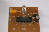 Inside
the Pioneer CU-P0069 there is nothing much other than a 4-bit
microcontroller, the
NEC
D6600ACS-C14. This is a custom maskable controller and is
preloaded with the required program and data (type C=14) for Pioneer CD
players and is the cheapest solution for Pioneer mass production.
The datasheet for a close relative, the
NEC 6122 gives more information
about the NEC protocol and shows how a replacement handset could be built for
any pioneer device that you know the codes for. It is of course a
shame that all this information wasn't as easily available as it is now
when I was first trying to work this all out form scratch with a knife and
a bear skin in 1994! Inside
the Pioneer CU-P0069 there is nothing much other than a 4-bit
microcontroller, the
NEC
D6600ACS-C14. This is a custom maskable controller and is
preloaded with the required program and data (type C=14) for Pioneer CD
players and is the cheapest solution for Pioneer mass production.
The datasheet for a close relative, the
NEC 6122 gives more information
about the NEC protocol and shows how a replacement handset could be built for
any pioneer device that you know the codes for. It is of course a
shame that all this information wasn't as easily available as it is now
when I was first trying to work this all out form scratch with a knife and
a bear skin in 1994!
Pioneer SR Bus
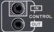
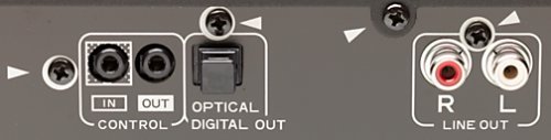 Most
Pioneer equipment has a bus that can be connected from unit to unit that
is called SR, short for System Remote and is marked CONTROL IN and OUT as
shown to the left. This enables several units to be connected
together and operated from a common receiver. Not all Pioneer
equipment has this connector, like the UK market PD-F100 CD Changer or the
SP-700D Soundfield Processor for example, but most do. This is
simply a TTL +5V rail supplied by the receiving end (CONTROL IN).
The sending end (CONTROL OUT) pulls this rail down to 0V (GND) with pulses
that are the same as the NEC protocol described above except that the
pulses are unmodulated, that is there is no 40kHz carrier inside each
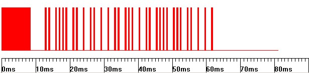
pulse, its just a solid period of 0V. So the pull down sequence looks
just like the red patterns shown in the Complete Frame Transmission section
above except that it is inverted where the top of the pattern (resting part)
would be +5V and the bottom (pulse part) would be 0V as shown below. Most
Pioneer equipment has a bus that can be connected from unit to unit that
is called SR, short for System Remote and is marked CONTROL IN and OUT as
shown to the left. This enables several units to be connected
together and operated from a common receiver. Not all Pioneer
equipment has this connector, like the UK market PD-F100 CD Changer or the
SP-700D Soundfield Processor for example, but most do. This is
simply a TTL +5V rail supplied by the receiving end (CONTROL IN).
The sending end (CONTROL OUT) pulls this rail down to 0V (GND) with pulses
that are the same as the NEC protocol described above except that the
pulses are unmodulated, that is there is no 40kHz carrier inside each
pulse, its just a solid period of 0V. So the pull down sequence looks
just like the red patterns shown in the Complete Frame Transmission section
above except that it is inverted where the top of the pattern (resting part)
would be +5V and the bottom (pulse part) would be 0V as shown below.
Pioneer SR Bus CD Play Button
+5V
0V
|
 |
 Note that
the tip pin of the CONTROL jack plug is the SR bus pin and the ground connection
between the units needs to be made with an audio ground from the LINE
IN/OUT connectors. The sleeve connection on the jack plug is used
for connecting digital audio between players that support it. From
this it can be seen that it would be quite easy to interface a computer
directly to the bus although as I mentioned above, as not all Pioneer
equipment has this connector and other manufacturers all have their own
scheme (or nothing at all),
PCRemote uses an optically
connected carrier based system for transmission just like a regular
Learning Remote. Also, there is no addressing scheme on this bus so
if you have more than one CD player connected, both players will respond to the
commands given on the bus if all the players are just connected together. Note that
the tip pin of the CONTROL jack plug is the SR bus pin and the ground connection
between the units needs to be made with an audio ground from the LINE
IN/OUT connectors. The sleeve connection on the jack plug is used
for connecting digital audio between players that support it. From
this it can be seen that it would be quite easy to interface a computer
directly to the bus although as I mentioned above, as not all Pioneer
equipment has this connector and other manufacturers all have their own
scheme (or nothing at all),
PCRemote uses an optically
connected carrier based system for transmission just like a regular
Learning Remote. Also, there is no addressing scheme on this bus so
if you have more than one CD player connected, both players will respond to the
commands given on the bus if all the players are just connected together.
CD-DECK SYNCHRO Bus

Another connector worth mentioning to complete the control picture is
the CD-DECK SUNCHRO jack. This is normally used to connect between
Pioneer CD players and Cassette decks. The tape deck can be set to
start and stop recording when the CD player starts play and stop when CD
play stops. The bus is again a simple +5V TTL rail that is held high
by the receiver (The tape deck). When the CD player (the sender) is
playing, it pulls the rail down to 0V (GND). Again as with the SR
bus described above, the ground connection between the two units is made
with audio ground. When play stops, the CD player releases the rail
and it goes back to its normal +5V state. Here again though, Pioneer
are inconsistent in that this connector is not provided on all CD players
(the PD-F1009 plus several others) but this is clearly a
useful jack to monitor with a computer control application like
PCRemote so that it knows when CD
play has ended for sure. On
CD Changers that do not have
this jack, monitoring the voltage on the chucking motor does just as well
although it requires drilling a hole in the back of the player to fit the
new jack!
|